The INEOS Grenadier exterior utility belt runs L-Track slots with a practical 15–25 kg per attachment point (off-road derated). Here's what that means for real builds, why the OEM anodized finish fades in UV within 1–2 seasons, and which fittings actually engage the rail.
The INEOS Grenadier ships with something unusual for a factory vehicle: external L-Track mounting rails running along the body flanks. In the cargo and aviation industries, L-Track is the standard for securing loads that shift under dynamic forces — pallets in turbulence, motorcycles on flatbeds, stretchers in ambulances. Bolting it to the outside of an off-road vehicle was a deliberate engineering statement: this truck was designed to carry serious gear on its skin, not just inside its cabin.
But somewhere between the engineering intent and the real-world execution, two problems emerged. First, owners discovered that the anodized finish on the OEM rails degrades faster than expected when exposed to UV and trail abuse. Second, the community discovered that fitting accessories to these rails isn't quite as plug-and-play as the L-Track standard implies. Both problems trace back to materials science decisions made during manufacturing — and both have solutions rooted in the same discipline.
This is a technical analysis of how L-Track works, what it can hold, why finishes fail, and what the engineering options look like for Grenadier owners building out their utility belt systems.
Quick Answer: Grenadier Exterior Utility Belt — Key Numbers
- Per-slot working load: 15–25 kg single-stud attachment, 30–40 kg multi-point bracket spanning 2–3 slots (derated from 600 kg rated; off-road dynamic loading applies)
- Six mount positions: 3 per side — front door, rear door, rear trunk. Rear trunk positions sit on steel quarter panels; door positions are aluminum. Heavy gear (jerry cans, recovery boards) always goes on steel rear-trunk rails.
- OEM anodizing (Type II sulfuric): Fades from black to grey within 12–24 months of UV exposure — organic dye degrades inside the pore structure. Powder coat (60–80 µm) or Type III hard-anodize resists indefinitely.
- Fitting compatibility: Not all L-Track fittings engage the Grenadier's extrusion geometry. Verify stud width and slot-shoulder dimensions before buying generic marine or cargo hardware.
L-Track Engineering: What You're Actually Bolting To
L-Track (also called airline track or logistic track) is a slotted aluminum extrusion originally developed for the aviation cargo industry. The profile consists of a continuous channel with regularly spaced keyhole slots — typically on 2-inch (50mm) centers — that accept single-stud or double-stud twist-lock fittings. Insert the stud, rotate 90 degrees, and the fitting locks against the internal shoulder of the slot. The standard behind this geometry traces to cargo restraint specifications like AS/NZS 4535 and SAE AS36100, though most automotive applications reference the more general SAE J-track specifications.
What matters for Grenadier owners is the load rating at each attachment point. Standard L-Track in 6061-T6 aluminum — the alloy used in virtually all automotive and light commercial applications — provides a working load limit (WLL) of approximately 1,333 lbs (605 kg) per single-stud fitting, with a breaking strength of 4,000 lbs. Double-stud fittings, which engage two adjacent slots simultaneously, jump to a WLL of 2,833 lbs (1,285 kg) with a breaking strength of 8,500 lbs. These numbers assume proper installation to a rigid substrate — which is where vehicle-mounted track differs from floor-mounted track in a van or aircraft.
The Mounting Substrate Problem
When L-Track is bolted to a steel cargo floor with through-bolts and backing plates, the substrate is rigid enough that the track's rated capacity is the limiting factor. On a vehicle exterior, the substrate is a body panel — aluminum in the Grenadier's case for the doors, steel for the quarter panels. The practical load capacity of each rail segment is therefore limited not just by the track's slot strength, but by the panel's ability to resist the moment arm created by cantilevered weight hanging off the vehicle's flank.
This is why INEOS engineered threaded inserts (nutserts) into the body at each mounting position rather than relying on self-tapping screws or adhesive. The nutserts distribute clamping force across a larger footprint on the backside of the panel, and the bolt preload creates a friction-locked joint that resists both shear (side-to-side) and tensile (pull-away) forces. It's a detail that owners who've worked on vans or truck caps will recognize — and one that matters enormously for vibration resistance over thousands of miles of corrugated dirt roads.
Why slot spacing matters for load distribution
When you mount a heavy accessory — a loaded 20L jerry can weighs roughly 18 kg (40 lbs) — the force isn't just straight down. Vehicle dynamics create lateral, longitudinal, and vertical acceleration loads. A 20 kg static load experiences 2–3g lateral force during aggressive off-road driving, producing 40–60 kg of dynamic shear at the fitting. Distributing that force across two or three L-Track slots (using multi-point brackets) drops the per-slot load by half or two-thirds. This is why well-engineered accessory carriers use wide attachment footprints rather than single-point clamps.
The Fitting Compatibility Issue
A recurring frustration on owner forums involves L-Track fitting compatibility. Several owners have reported that generic L-Track fittings — purchased from marine or cargo suppliers — don't engage cleanly with the OEM rail slots. One owner on The Grenadier Forum described attempting to insert standard L-Track studs into the exterior bars and finding them incompatible, while another noted that the pre-drilled screw patterns on aftermarket track sections don't match the Grenadier's mounting point spacing.
This isn't unusual. While "L-Track" describes a general profile family, there's meaningful dimensional variation between manufacturers. Slot width, slot depth, and the internal shoulder geometry can vary by fractions of a millimeter — enough to prevent engagement with fittings designed for a different manufacturer's extrusion. The stainless steel T-nut solution that's gained traction in the community — using tapped T-nuts with positioning clips instead of traditional twist-lock studs — sidesteps this compatibility issue by engaging the track channel itself rather than the individual slots.
The Chemistry of Finishes That Fail
This is the section that explains why your utility belt rails look washed out after a year in Arizona or Queensland, and why the owner next to you at the trailhead with different rails doesn't have the same problem. It comes down to two fundamentally different approaches to protecting aluminum surfaces from photodegradation.
Type II Sulfuric Acid Anodizing: The OEM Approach
Anodizing is an electrochemical process, not a coating in the traditional sense. The aluminum part is submerged in a sulfuric acid electrolyte bath and connected as the anode in an electrical circuit. As current flows, oxygen ions from the electrolyte combine with aluminum atoms at the surface to form aluminum oxide (Al₂O₃) — a ceramic layer that grows into the base metal rather than sitting on top of it.
Type II anodizing, which is standard for architectural and consumer products, produces an oxide layer 5–25 µm thick. The layer is porous when first formed — those pores are what accept dye molecules when the part is colored black — and then sealed in a hot water or nickel acetate bath that hydrates the oxide and closes the pores. The result is a hard, integrated surface that resists abrasion, doesn't peel (because it is the base metal, chemically transformed), and provides good corrosion resistance.
So why does it fade?
The black color in anodized aluminum comes from organic dye molecules trapped in the pore structure. UV radiation breaks down these organic compounds through photolysis — the same mechanism that fades fabric and painted surfaces. But unlike paint, you can't simply "re-coat" anodized aluminum. The dye is embedded in a ceramic matrix. Once the dye degrades, the surface transitions from black to a progressively lighter grey as the underlying aluminum oxide (which is naturally transparent-to-white) becomes the dominant visual surface. The sealed pore structure that makes anodizing durable also makes it impossible to re-dye without stripping the entire oxide layer and starting over.
In salt spray testing — the ASTM B117 accelerated corrosion test used industry-wide — Type II anodizing typically survives 336 hours before showing visible degradation. That sounds like a lot until you compare it to the alternatives.
Thermoset Powder Coating: A Different Strategy
Powder coating is an entirely different material system. Dry polymer powder — typically polyester, polyurethane, or an epoxy-polyester hybrid — is electrostatically sprayed onto the part and then cured in an oven at 180–200°C. The heat melts the powder and triggers a cross-linking reaction that transforms it into a continuous thermoset film. Unlike thermoplastics, thermosets don't re-melt; the cured coating is chemically locked.
The resulting film is 60–80 µm thick — three to four times the thickness of a Type II anodized layer. But thickness alone isn't why powder coat outperforms anodize in UV environments. The critical difference is the UV resistance mechanism. Powder coat formulations include UV stabilizers — typically hindered amine light stabilizers (HALS) and UV absorbers (benzotriazoles) — that are distributed throughout the film thickness. As the outer surface of the coating absorbs UV energy, these stabilizer molecules sacrifice themselves to prevent chain scission in the polymer backbone. The coating degrades from the outside in, micron by micron, over years rather than months.
In salt spray testing, quality powder coatings on properly pretreated aluminum achieve 500–1,000+ hours before visible corrosion. The pretreatment step is critical: chrome or chrome-free conversion coatings create a chemical bond between the aluminum substrate and the powder, preventing underfilm corrosion that causes blistering and delamination.
Why the Dual-Finish Approach Matters
DVA's utility belt rails use both processes in sequence: anodize first, then powder coat over the anodized surface. This isn't redundant — each layer serves a distinct purpose. The anodized oxide layer provides an excellent adhesion surface for the powder coat (the porous ceramic texture gives the polymer something to grip mechanically and chemically). It also serves as a secondary corrosion barrier if the powder coat is ever penetrated by a deep scratch or stone chip. The powder coat provides the UV stability, impact resistance, and aesthetic durability that anodize alone cannot deliver in an exterior application.
For owners in coastal environments — where salt air accelerates both UV degradation and galvanic corrosion — the dual system addresses both attack vectors simultaneously. For desert owners dealing with extreme UV indices and abrasive sand, the thick polymer layer absorbs impacts that would fracture a thin anodized surface. Neither finish alone is optimal for the punishment an exterior utility belt absorbs. The combination is.
The real-world timeline
Forum reports from owners in high-UV climates (southern US, Australia, Middle East) consistently describe visible fading on anodized OEM rails within 8–14 months. The front-facing and top-facing surfaces of the rails show it first — exactly where UV exposure is highest. Several owners chose the plain bump strips specifically to avoid the discoloration issue after hearing early complaints. Others report chemical staining from car wash detergents reacting with the anodized layer — a problem that doesn't occur with powder-coated surfaces because the polymer film is chemically inert to alkaline cleaners.
OEM vs. Aftermarket: The Specification Comparison
- ✓ L-Track profile
- ✓ 6061-T6 aluminum
- ⚠ Anodized finish only (5–25 µm)
- ✗ UV fade within 8–14 months
- ⚠ Chemical sensitivity to alkaline cleaners
- ⚠ ~336 hr salt spray resistance
- ⚠ Trim-dependent availability
- ✗ Dealer retrofit only
- ✓ L-Track profile
- ✓ 6061-T6 aluminum
- ✓ Anodized + Powder Coat (60–80 µm)
- ✓ UV-stable with HALS protection
- ✓ Chemical resistant to common cleaners
- ✓ 500–1,000+ hr salt spray resistance
- ✓ 6 positions available regardless of trim
- ✓ Direct bolt-on to factory nutserts
| Specification | OEM | DVA |
|---|---|---|
| Track Standard | L-Track (proprietary dimensions) | L-Track (standard dimensions) |
| Alloy | 6061-T6 aluminum | 6061-T6 aluminum |
| Finish System | Type II sulfuric acid anodize | Type II anodize + thermoset powder coat |
| Total Finish Thickness | 5–25 µm | 60–80 µm |
| UV Degradation Mechanism | Organic dye photolysis (irreversible) | HALS-stabilized polymer (sacrificial) |
| Salt Spray (ASTM B117) | ~336 hours | 500–1,000+ hours |
| Impact Resistance | Brittle fracture (ceramic layer) | Elastic deformation (polymer film) |
| Mounting | Factory nutserts | Same factory nutserts — direct swap |
| Full Set Price | Varies by dealer/market | $499 |
The Accessory Ecosystem: What You Can Actually Mount
The utility belt is infrastructure. It doesn't do anything until you attach things to it. But the engineering of those attachments — how load transfers from accessory to fitting to track to body panel — determines whether your build is robust or a liability on a washboard road at speed.
Load Math for Common Configurations
A single L-Track slot handles roughly 600 kg of working load in a test fixture. On a vehicle, derate that significantly — the body panel, fastener quality, and dynamic loading environment mean a practical limit of 15–25 kg per single-stud attachment point for sustained off-road use, or roughly 30–40 kg for multi-point brackets spanning two or three slots. These aren't manufacturer ratings; they're practical guidelines based on what the mounting substrate and vibration environment will tolerate long-term without fatigue cracking around the nutserts.
Within those limits, here's what owners are actually running:
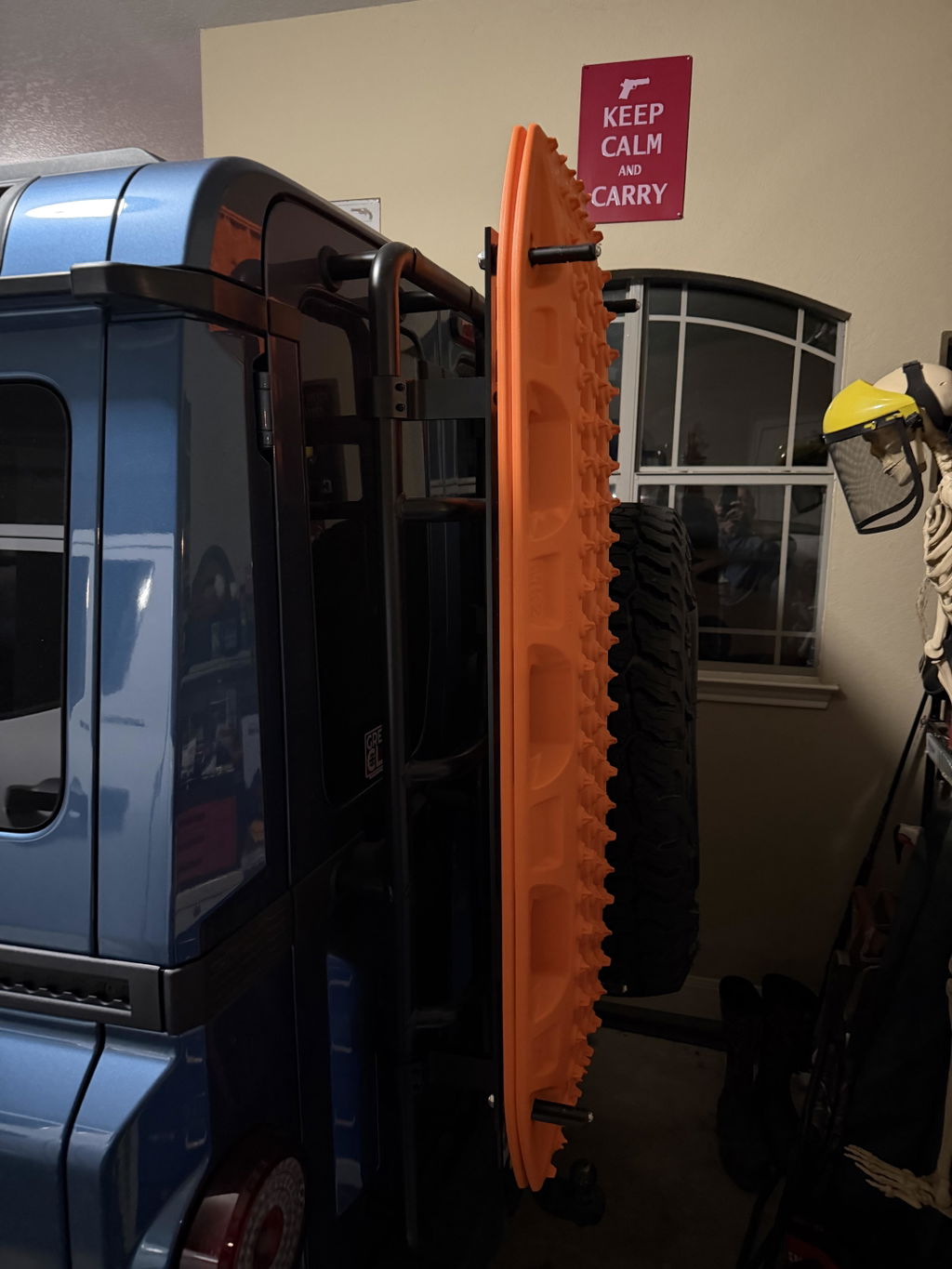
Recovery boards (MaxTrax / TRED): 3–4 kg per board, mounted in pairs. Well within single-carrier limits. The challenge is aerodynamic — flat boards mounted perpendicular to airflow create significant drag and noise above 100 km/h. Carriers that mount boards flush against the body panel (rather than standing proud) solve this.
20L jerry cans: 1.5 kg empty, 18 kg full of fuel, 21 kg full of water. Two cans (one per side on the rear trunk positions) adds 36–42 kg of liquid capacity without touching interior cargo space. The key engineering detail is that the carrier must prevent the can from swinging on its mount — a pendulum load on a cantilevered bracket amplifies forces at the track attachment point during cornering and braking.
MOLLE panels: The panel itself weighs 1–2 kg. Loaded with pouches, tools, and organizers, a working MOLLE panel runs 5–10 kg. Well within limits, but the distributed nature of MOLLE loads (many small items across a large surface) means the panel's own mounting to the L-Track needs to prevent racking — the panel twisting on its attachment points when the vehicle rolls.
Camp tables and fold-out work surfaces: These are moment-arm problems. A table that extends 40cm from the vehicle body with 5 kg of gear on it creates a bending moment at the L-Track attachment point. Multi-point mounting with wide spacing is non-negotiable here — the wider the attachment footprint, the lower the stress at each individual fitting.
MOLLE Integration: Two Mounting Philosophies
The overlanding community has adopted MOLLE (Modular Lightweight Load-carrying Equipment) webbing from military logistics, and it shows up in two forms on utility belt builds. The first approach mounts a rigid MOLLE panel to the L-Track — a flat plate with PALS webbing that accepts standard pouches. The second approach integrates MOLLE into a multi-function carrier that combines the panel with other features (fold-out table, Jerry can bracket, tool holders).
The engineering advantage of MOLLE is load distribution. Instead of concentrating 10 kg at a single point, MOLLE spreads it across dozens of small pouches and attachment points, each carrying a few hundred grams. The weak link becomes the MOLLE panel's own attachment to the L-Track — which brings us back to multi-point brackets and proper anti-racking design.
Installation Engineering: Bolt-On Details That Matter
The Grenadier's factory nutserts make utility belt installation a straightforward bolt-on affair — in theory. In practice, the details of how you torque those bolts determine whether the rails stay tight after 20,000 km of mixed terrain.
Thread-Locking Strategy
Every bolt on an off-road vehicle is subject to vibration-induced loosening (Junker's effect). The Grenadier's body panels flex under torsional loads, and the utility belt rails sit on the exterior where thermal cycling adds expansion/contraction stress to the joint. Medium-strength threadlocker (Loctite 243 or equivalent) on each fastener is not optional — it's what separates a bolt-on install from a rattle-and-retorque cycle every few thousand kilometers.
Some owners on forums have reported OEM utility belt fixings that weren't straight from the factory — a quality control issue that suggests inconsistent torque application during assembly. For aftermarket installations, a calibrated torque wrench and the manufacturer's spec eliminate this variable entirely.
The Bolt-On Advantage
It's worth noting what this installation isn't: it's not riveted, welded, or adhesive-bonded. Bolt-on attachment to factory nutserts means complete reversibility — remove the rails and the vehicle is returned to stock with no evidence of modification. This matters for lease returns, warranty considerations, and owners who may want to reconfigure positions as their accessory needs evolve. It also means a failed fastener can be replaced individually rather than requiring professional repair to a permanent attachment method.
For owners without OEM rails — those who configured their Grenadier without the utility belt option or received a trim that didn't include it — the factory mounting points are still present on every body. The threaded inserts are installed during body assembly regardless of whether rails are ordered. Bump strips occupy the same mounting positions on non-utility-belt configurations and use the same fastener locations.
Six Positions: Mapping the Build
The Grenadier's body provides six discrete utility belt mounting locations — three per side. Each position has different characteristics based on rail length, proximity to doors, and exposure to trail hazards:
An important detail: the rear trunk positions are on steel quarter panels, while the door-mounted positions are on aluminum body panels. Steel is stiffer and heavier, meaning the rear trunk positions handle cantilevered loads better than the door positions. This is why experienced builders put their heaviest accessories (full jerry cans) on the rear trunk and lighter gear (MOLLE panels, lights) forward.
Configuration Options and Build Strategy
Not every build needs all six positions on day one. DVA offers the utility belt in three configurations, each using the same L-Track extrusion and dual-finish process:
The modular approach is deliberate. Start with the rear set for recovery gear and jerry cans, add the front set later for lighting — or go full set from day one if you already know your build plan. All configurations bolt to the same factory nutserts with no adapter brackets or modification.
A Reference Build: Overland Touring Configuration
4,000 km Unsupported Desert Crossing
- FRONT · BOTH L-Track sliders with auxiliary LED pods for trail lighting — low profile, minimal drag
- REAR · PASS MOLLE camp table — food prep surface, laptop work station, tool organization in PALS pouches
- REAR · DRIVER Side Accessory Carrier Gen 2 with MaxTrax recovery boards — flush-mounted for reduced aero drag
- TRUNK · DRIVER 20L NATO jerry can carrier — fuel (40 km additional range per can at 12 L/100km)
- TRUNK · PASS 20L NATO jerry can carrier — water (critical redundancy for remote travel)
Total added external weight: approximately 55 kg fully loaded. Recovery capability, camp functionality, 40L of additional liquid capacity, and trail lighting — none of it consuming interior cargo volume. Reconfiguration for different trip profiles takes 15–20 minutes with basic hand tools.
Build Planning: What the Community Has Learned
After two years of Grenadier builds across forums and owner groups, a few patterns have emerged that are worth documenting:
Heavy gear goes rear. The rear trunk positions are on steel, closer to the rear axle, and less affected by door-opening clearance. Every experienced builder puts jerry cans on the trunk positions. Recovery boards go on the rear door positions. Lights and comms go forward. Fighting this layout usually means fighting physics.
T-nuts over twist-lock studs. The community has largely converged on tapped T-nut hardware (stainless steel, with positioning clips) over traditional L-Track twist-lock fittings for permanent accessory mounts. T-nuts provide a threaded attachment point that accepts standard bolts, allowing precise torque control — something twist-lock fittings can't provide. For accessories that need to slide and reposition frequently, twist-lock studs still make sense.
Check fitment before buying generic fittings. As noted earlier, not all L-Track is dimensionally identical. Hardware that fits aviation L-Track may not engage the Grenadier's extrusion profile. The safest approach is using fittings verified against the specific track — either from the vehicle manufacturer's accessory ecosystem or from aftermarket suppliers who have confirmed dimensional compatibility with the Grenadier. DVA's Grenadier L-Track hardware is dimensionally verified for the OEM exterior utility belt rail profile, covering sliders, tie-down rings, gear hooks, and M8 bolts purpose-made for the Grenadier's slot geometry.
Budget for the full set. Owners who start with two positions invariably add more. The per-position cost of the full set at $499 is significantly lower than buying the front ($259) and rear ($199) sections separately. If there's any chance you'll want all six positions within the first year, the math favors buying once.
The finish question settles itself over time.
Park two Grenadiers side by side — one with anodized rails, one with dual-finish rails — and they'll look identical on day one. The difference shows up at month eight, month fourteen, month twenty-four. Anodize fades gradually enough that owners don't notice until they see a photo of their truck from the first week. By then, the only fix is replacement. The materials science isn't ambiguous here: organic dyes degrade under UV; HALS-stabilized thermoset polymers resist it. The rest is just waiting.